Minimum and maximum
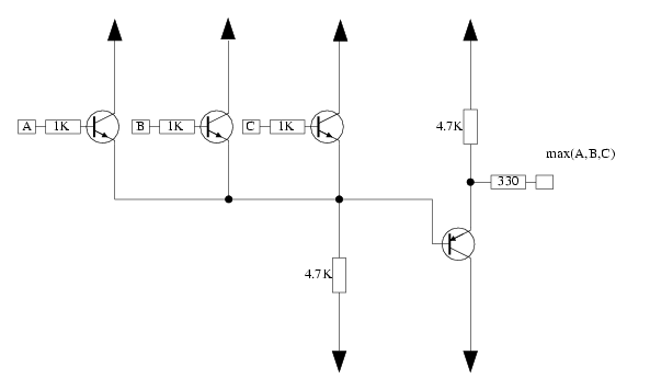
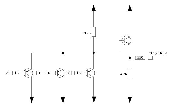
These two circuits give the maximum and minimum of several voltages. Three inputs are shown, but it can be extended to arbitrary lengths. The input transistors act as emitter followers, and the output stage is a complementary emitter follower, in an attempt to minimize any voltage shifting. The transistor type is not indicated, because any small signal transistors will work for this. One interesting usage for this would be full wave rectification, it can easily be done when a signal and an inverted version of a signal would be presented to either of the max or min circuits. These aren't terribly accurate, as the emitter followers have some offset, and also the gain isn't unity.
Also these can be used as logic gates performing the OR and AND functions for trigger or gate voltages.
They are quite similar in Function to the Serge Peak and Through Module.
Maximum circuit:

Minimum circuit:


