


A tutorial on exponential convertors and temperature compensation
In order to broaden the knowledge about this frequently employed circuit, I provide this discussion here. To understand this document I will provide you with the needed knowledge about transistors. A little maths is involved however, mainly log and exp laws. I don't give all the derivations, if you're not into maths, then take the results for god given ;-)
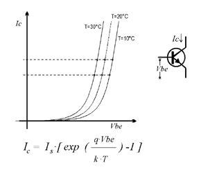
In Figure 1 you see the dependancy between Vbe and Ic,
for a single transistor, as well as its
mathematic form, the Ebers Moll equation. From the equation (and even more from the graph) you can see that
Ic relates exponentially to Vbe. This is already what we want, but there is one problem hidden in the equation.
Is (the collector leakage current) is largely dependant upon temperature. Infact it doubles for a 10 degrees
temperature increment. There is a second temperature dependancy in the argument of the exp function,
which we'll discuss later. k is the Boltzmann constant, and q the charge of an electron.
One can use
this relationship between Ic and Vbe directly if one keeps the transistor at constant temperature.
This could be done if the circuit is kept at some stable elevated temperature. In uncritical applications,
like VCAs, one occasionally sees a single transistor as exponential current source.
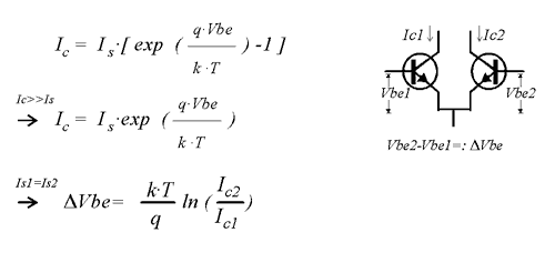
To get rid of the temperature dependancy of Is one can use a second transistor as shown in Figure 2. The trick is that for the *difference* in the two Vbe's Is plays no role. Look at the two points on the leftmost graph in Figure 1. "Read" the collector currents at the two points, and imagine the corresponding difference for Vbe. Now look at the same Ic's on the other graphs and read the corresponding Vbe difference. They are the same. This is the way the first order temperature effect is cancelled. Of course one can put this into a more mathematical form, which I included in Figure 2. It shows that the logarithmic ratio of currents is proportional to the difference in Vbe. Or put the other way round (if one of the two currents is held fixed): Ic relates exponentialy to delta Vbe. Now to meet the requirement that one of the transistors has a fixed current, one uses a current source. In a simpler form a resistor can be used, forcing some current into the collector (This has drawbacks however, the voltage over the resistor will vary with the input. So the current won't be fixed. One sees this in less precise convertors for Q control or the like) One can see that the current at the other collector is proportional (for a fixed Vbe) to this current. When delta Vbe = 0 the current in both transistors is equal. The circuit is a current mirror then. One can also see that one can use this reference current to linearly modulate the current at the output. I.e. linear FM in VCOs.
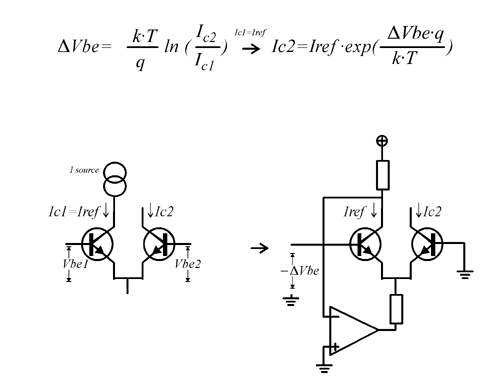
A more elaborate circuit is the one of Figure 3, which is the familiar exponentiator. Here the opamp is used as a current source to hold the current thru one of the transistors fixed. (Ic would vary in the simpler resistor circuit.) Theoretically one can use either bases to put the control voltage in, but usually the left one is used because it makes less demand on the driving impedance which would have to be very low for the other one. As you may notice Vbe goes the other way round than in the circuit above. So in the circuit shown, the output current increases for input voltages going towards the negative supply. Hence an inverting opamp amplifier is usually added (which is handy because you can sum up many signals here). The opamp shown is just a current source. The upper resistor determines the reference current (Iref=Vsupply/R). The lower resistor delimits the maximum current thru the exponentiator. Around 1-4 kOhms is normally used. The maximum output current is approximately the opamps negative saturation voltage divided by the value of the resistor. This is of course only true for currents lower than the maximum output current for the opamp. The equation given for Ic2 shows there is still temperature dependancy. This is a second order effect. The above discussion has eliminated the first order effect, the equation is independant of Is now. We see that the scaling is still temperature dependant, that is the wanted 1V/octave scaling messes up with temperature, thus at drifting temperatures the VCO frequency could change, and the octaves would be squashed or stretched, this is of course undesirable. From the right equation one can see an important fact, if deltaVbe = 0, then the argument of the exp function is zero, and independant of temperature. The exponentiator has the lowest temperature dependancy when operated arround the reference current. This means that one can improve stability, by choosing the reference current appropriately. One should choose the current so that it gives a frequency in the region where the design should be most stable. From the relation C=I*t/V you should be able to figure out what the frequency will be for a particular current.
The whole discussion so far relies on that the transistors are at the same temperature. This is the reason why transistors are used which are on the same chip.
There is one little thing that is left out in the above discussion: the effects of Rbulk (or rBE). But it should suffice to say, that for the best performance of the exponentiator circuit a transistor pair with low rBE should be used. Here you find rBE values for various transistors. Usually some form of compensation is required, in a VCO one frequently does that using the HFT (high frequency trim, Franco Resistor) which while actually a compensation for the finite reset time, allows to trim out errors due to rBE as well.
A direct aproach to compensating effects of Rbulk is to feed the voltage from the output of the opamp, back to the base of the pair via a high value variable resistor and a diode. The idea is attributed to Dave Rossum, often called Rossum compensation. My personal variation on this is this circuit. The unlabeled resistor at the bottom is a high value resistor of 1Meg or so, the value depends on how large rBE is. The improvement to the original Rossum compensation method is that by by making the trimmer value equal to the one hanging at the emitters, the diode sees a varying current that is a copy of the one through the output transistor, so the forward drop more closely resembles the one at the transistor. And due to the grounding of one end of the trimmer, one can set the amount of compensation even to zero. Conveniently now the circuit does not detune much while adjusting the compensation. Note: ignore the values for the input divider, they were special to the circuit I pulled this snippet from.
What else do we yet have to compensate? As we see the only remaining temperature dependancy is in the argument of the exponential function. KT/q has the dimension of a voltage, which is 25mV arround room temperature. That is when deltaVbe falls 25mV the current is 2.73 (e) times greater. So when scaling this to give the input change for the output doubling the current, we want octaves, we get ln(2) * 25mV= 17.3mV. So we will have to divide down our 1V/oct input down to be 17.3mV for 1V. KT/q which is also called Vt is dependant of temperature. So when the temperature falls, Vt gets smaller, and for raising temperature Vt gets larger. Thats not what we want, we want an octave to be 1V in winter as in summer.
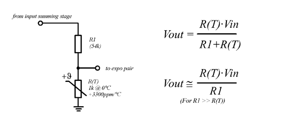
To compensate the 1/T dependancy in the argument of the exp function one has to find a way to make the input voltage proportional to T, because T/T gives unity. The classical method is by a so called tempco resistor. That is a resistor made from a material whose resistance varies (almost) linear with absolute temperature. Platinum has about the right temperature coefficient, and so this material is often used. Now we see how it works in the figure. The voltage across the tempco-resistor is used as the input for the exponentiator. As one can see, there is a small error - R(T) is also in the denominator - but when the resistance of the upper resistor is much larger than that of the Pt-resistor this error vanishes. Usually R1 has a value of 54k, and 1k tempcos are common, giving negligible error. This combination of values put us already near the needed divison for 1V to 17mV for the expo convertor. (Of course a trimmer would be included. And other values might be used, like 5.4k/100ohms.) There is another way of using the tempco: One can use it as the feedback resistor of an opamp, thus giving a gain of that circuit which is proportional to T. But this is usually avoided, because tempcos have (one must say had, with newer types) inductance, and you introduce errors from the opamps output voltage drift. It works when you use opamps with very low drift.
There are a number of alternatives to the tempco resistors. These methods were developed since tempcos were difficult to obtain, although that has changed now. The most popular method is to heat the whole chip which contains the transistors for the expo convertor. The famous uA726 did that, and there are a number of circuits which employ a heated CA3046. Another method which was used in one of the famous CEM chips is to accomplish the "linear rising gain with temperature" with a multiplyer. This can be done easily on the chiplevel, while its somewhat difficult to do on the boardlevel. The tempco amp elsewhere on this site does this. (I won't describe it in depth here because it has some problems with tuning accuracy.) It can be shown mathematically that the cancellation of temperature effects is perfect.
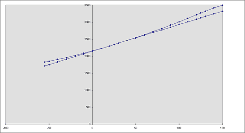
However I'd like to spend some words on the methods that I frequently use, because it uses components which are cheaper and easier to source. One must say that the performance of these methods is limited to a narrower range of operation temperatures. I came across the KTY 81-1xx series of devices made by Phillips. These are resistive temperature sensors, with a positive tempco. Only that the tempco behaves somewhat different than that of the Pt-resistors. When used with a series resistor of 1340 ohms, they act pretty much like a Pt-resistor of 2340 ohms. The Figure 5 shows that the resistance of KTY+1.34K behaves closely to the Pt-resistor (straight line) within a temperature range of 0°C to 50°C. (The numbers for that diagramm have been pulled from the KTYs datasheet, and calculated for the PT-resistor.) The errors approach 0.2% at the borders. The temperature range is sufficient for normal applications.
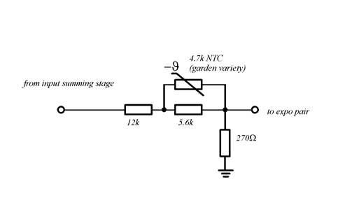
The last circuit I'd like to describe here is the NTC compensation circuit. Like with the KTY the temperature range is limited, performance is similar to it. The price is even lower, and these are available everywhere. I have done some comparisons between Pt-resistor, KTY, NTC and an "ideal" compensation, and I found that the performance for all three is comparable within the most interesting range of operation. For those interested to stare at the figures: Click here! (These are actually the gains vs. T of the circuits described here, multiplied with an appropriate factor to give nice range of the figures. Think of it as the Vbe for an arbitrarily chosen interval.)
René Schmitz
April 2000