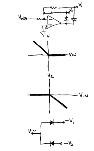
I. Basic circuit
Vin will be active when Vin < 0 volts and V1 will be active when Vin > 0.
It should be noted that the voltages are inverted from the input to the outputs.
The ideal diode circuit is equivalent to a pair of diodes except the pair of diodes does not invert the voltages. Real diodes would also have a fixed voltage drop. The ideal diode circuit, thanks to the opamp and the magic of negative feedback, eliminates this voltage drop. This is what makes the circuit ideal.
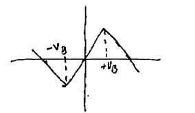
II. Full wave rectifier
The most common application of the ideal diode is the full wave rectifier. It works by summing one of the ideal diode outputs with the input.
One possible use is to convert a ramp into a triangle. Another possible use is as an envelope follower.
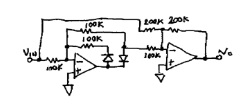
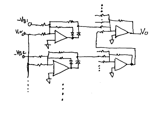
III. Piecewise linear functions
One of the most usefull functions of the ideal Diode is in piecewise linear functions. One application, for example, is a triangle to sine wave converter.
More basic functions are possible. As shown the gain can be made to reverse at Breakpoint. Very complex functions can be generated.
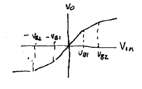
The basic circuit is shown below. Every Breakpoint requires an ideal diode circuit. Complex functions with lots of breakpoints will require a lot of ideal diode circuits.
IV. Practical Examples - Voltage Splitter
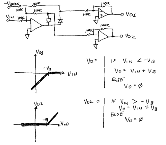
This is a very simple, straight forward application
of the ideal diode. I call it a voltage splitter because the input appears
on one output when VIN > -VB
and the other when VIN < -VB.
It should be noted that VB is
added to the input. For example, if VIN = 5 volts
and VB = - 4 volts you will get 2 volts on
VO2 and 0 volts on VO1.
You could subtract VBREAK from the outputs by adding in the inverse of
VBREAK to the two output opamps.
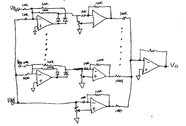
V. Practical Examples - Voltage Scanner
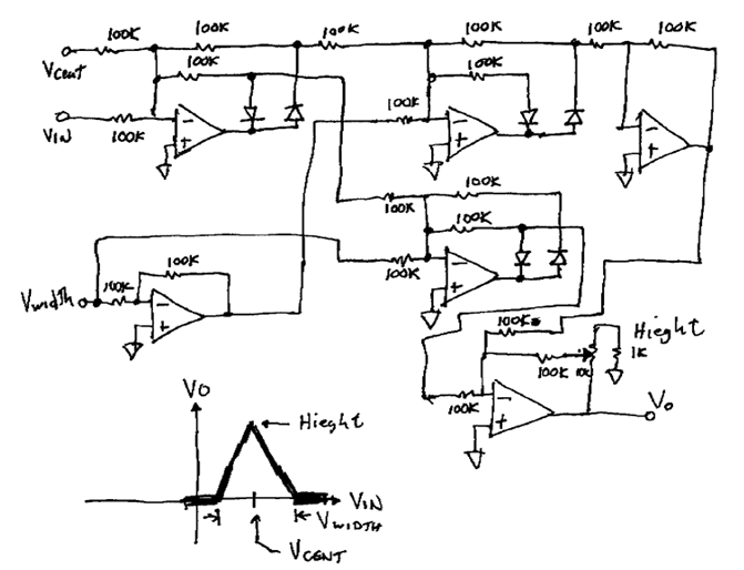
I call this one a voltage scanner because the function that is generated can be used to
control a VCA that is used to select a signal.
This implementation may or may not be the
simplest way to do the Job, but it is one way. It should be noted that you can substitute an OTA
for the height pot to obtain 100% voltage control.
The one advantage this circuit has
is that all the parameters are adjustable via voltage control.
It should also be noted that
this circuit uses the splitter.
VI. Practical Examples - Waveform Shaper