


Signal switcher
This circuit can be used to switch a pair of audio or CV signals to a common output. It uses standard CMOS switches in a configuration that does eliminate most of the distortion, and allows for full voltage range to be processed. The trade is that the switches are no longer bidirectional, but this is not really a problem. By using several of these, a lot of other switching configurations can be made.
Switching circuit:
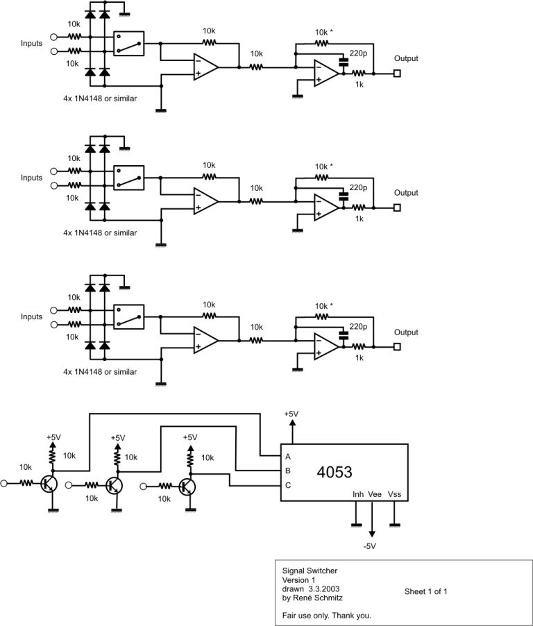
The input voltage is first converted into current, which is then switched, and converted back to voltage by running it into the virtual GND of an opamp. By this the switch sees only about 1/80th of the voltage it would see in a straight forward switching circuit, so distortion is reduced about to 1/80th of the direct circuit. (And that means practically none!) If you want to do critical CV switching, you could add a small 470 ohms trimmer in series with the feedback resistors of the output stage. (In the schematic they have a blurry spot which once was an asterisk near it.) With that you can set the gain precisely to 1.
Parts of the circuit must be powered from +-5V. Use a pair of 7805/7905 to generate that voltage. The opamps run on normal +-15V supplies. The diodes protect the unselected input of the switches, and must not be omitted. The transistors can be any standard types. Like BC548A,B or Cs. The OPs can be TL072 or anything else of your likeing. Although I did not test it, the switch IC could perhaps be also a 74HC4053, which has lower R(on), instead of a CD/HEF/HCF 4053.